
Inverted Pendulum on a Cart: Modelling, PID Control and Simscape Simulation
Inverted Pendulum on a Cart: Modelling, PID Control and Simscape Simulation



A cart–pendulum system modelled from first principles, stabilised with a PID controller in MATLAB/Simulink, and validated against a CAD-based Simscape Multibody model built from a SolidWorks assembly. Course project for Dynamics.
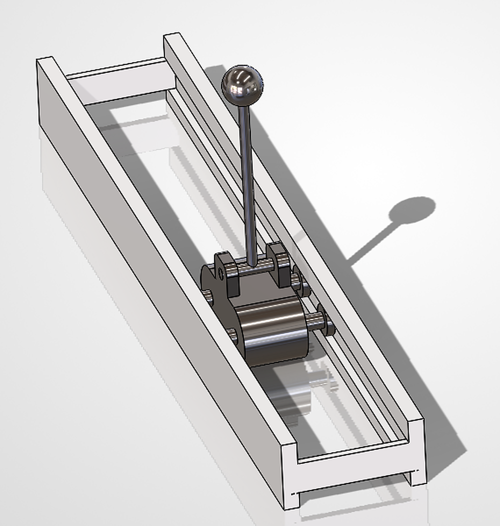
Overview
| Phase | What was done | Tools |
|---|---|---|
| 1. Analytical model | Equations of motion with the Lagrangian method, linearisation about upright, state-space model and transfer function | MATLAB, Symbolic Math Toolbox |
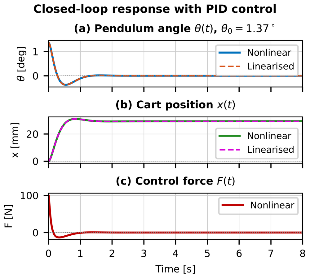
| 2. Control design | PID controller with filtered derivative, tuned for a 60° phase margin, simulated on the linear and nonlinear models | MATLAB, Simulink, Control System Toolbox |
| 3. CAD validation | SolidWorks assembly imported into Simscape Multibody, same PID gains, results compared with the analytical model | SolidWorks, Simscape Multibody Link |
Key results
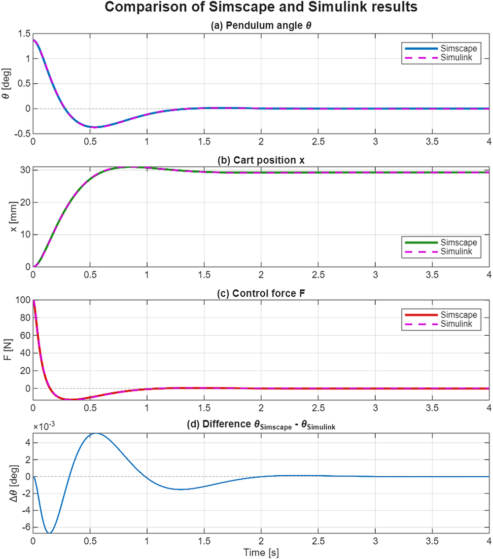
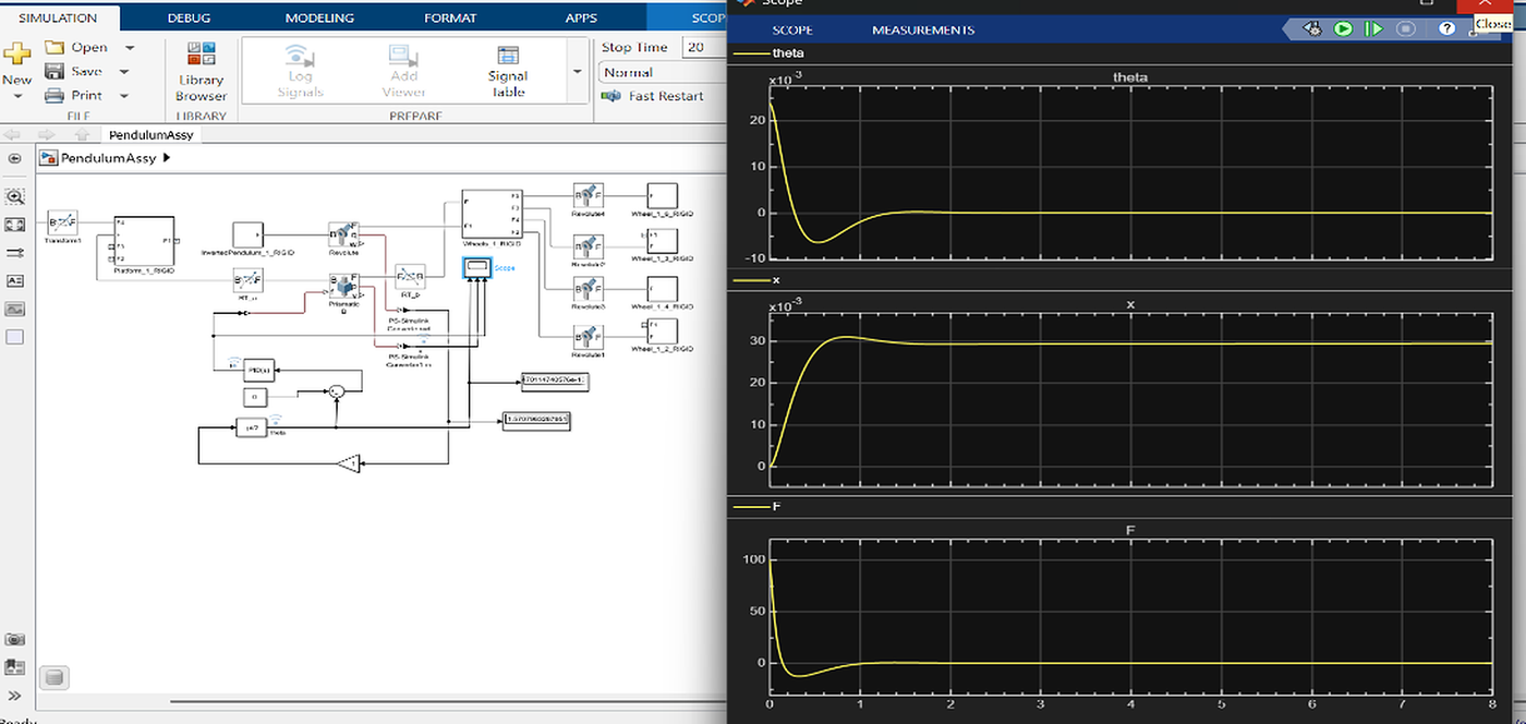
The upright pendulum is open-loop unstable (pole at +4.72 rad/s). The PID controller (Kp = −4192.9, Ki = −8365.6, Kd = −645.6, Tf = 0.01 s) balances it from the 1.37° tilt of the CAD pose:
| Metric | Simulink (analytical) | Simscape (CAD) | Difference |
|---|---|---|---|
| Settling time (2 %) | 1.219 s | 1.224 s | +0.4 % |
| Undershoot past upright | 27.43 % | 27.05 % | −1.4 % |
| Peak control force | 100.12 N | 99.97 N | −0.15 % |
| Cart peak / final position | 31.05 / 29.26 mm | 30.98 / 29.41 mm | −0.2 / +0.5 % |
The two models agree to within 0.0067° in pendulum angle (RMS 0.0014°). Phase margin 60°, peak sensitivity 1.16, and the loop stays stable for ±20 % changes in pendulum and cart mass.
More figures
**Simulink model and closed-loop response (Phase 2)**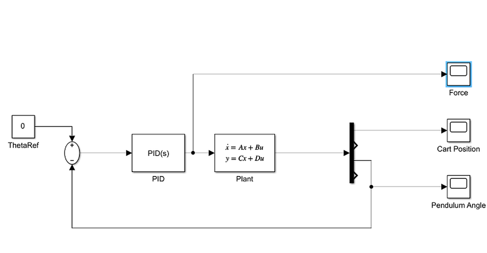
 **Simscape Multibody model and scope output (Phase 3)**
Repository structure
matlab/   MATLAB scripts, Simulink and Simscape models, data files, STEP geometry
cad/      SolidWorks assembly and parts
report/   Project report (PDF) and its LaTeX source
docs/     Figures used in this README
Keep every file in matlab/ in the same folder: the Simscape model loads the *_sldprt.STEP geometry files by name.
How to run
Requires MATLAB R2025b with Simulink, Control System Toolbox, Symbolic Math Toolbox and Simscape Multibody.
- Open MATLAB and set
matlab/as the current folder. derive_symbolic– derives the equations of motion and the A, B matrices.main_pid_inverted_pendulum– designs the PID controller, savespid_gains.mat, plots the response.build_simulink_pid_model– builds and runspendulum_pid.slx(scopes + results figure).PendulumAssy_DataFile, then openPendulumAssy.slxand press Run – CAD-based simulation with the 3-D animation.compare_pid_vs_assy– runs both models and produces the comparison figure and table.- Optional:
optimize_pidre-derives the gains;PendulumAssyDisturb.slxadds a torque disturbance.
Assumptions and limitations
Rigid bodies, planar motion, no friction or actuator limits, ideal sensors. The PID acts on the pendulum angle only, so the cart position is not regulated: after a disturbance the cart drifts. A cascade loop on cart position, or LQR, would fix this.
Author
Mary Sam: Dynamics course project, 2026.